Sfd And Bmd Of Beams - Civil engineering / SFD and BMD for Continuous Beam (MDM ... - I = second moment of area, in 4 or m 4;
byAdmin•
0
Sfd And Bmd Of Beams - Civil engineering / SFD and BMD for Continuous Beam (MDM ... - I = second moment of area, in 4 or m 4;. A simply supported beam is the most simple arrangement of the structure. E = modulus of elasticity, psi or mpa; Bendingmomentdiagram.com is a free online calculator that generates bending moment diagrams (bmd) and shear force diagrams (sfd) for most simple beams. The beam is supported at each end, and the load is distributed along its length. If p = 20 kn and l = 6 m, draw the sfd and bmd for the beam.
In sfd and bmd diagrams shear force or bending moment represents the ordinates, and the length of the beam represents the abscissa. L = span length under consideration, in or m; If p = 20 kn and l = 6 m, draw the sfd and bmd for the beam. Axial forces in beams ad and be are 10 kips and 15 kips respectively. The calculator is fully customisable to suit most beams;
SFD And BMD Diagrams | Shear Force And Bending Moment Diagram from sketchup3dconstruction.com The beam is supported at each end, and the load is distributed along its length. Bendingmomentdiagram.com is a free online calculator that generates bending moment diagrams (bmd) and shear force diagrams (sfd) for most simple beams. E = modulus of elasticity, psi or mpa; Consider the left or the right portion of the section. If p = 20 kn and l = 6 m, draw the sfd and bmd for the beam. 12) draw sfd and bmd for beam as shown below. Which is a feature unavailable on most other calculators. A simply supported beam is the most simple arrangement of the structure.
The beam is supported at each end, and the load is distributed along its length.
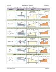
Jul 17, 2017 · below are the beam formulas and their respective sfd's and bmd's; 14) a 4 m long beam is shown in figure. 12) draw sfd and bmd for beam as shown below. It carries a load of 12 kn applied through a bracket and also a udl for 8 m length from reight end. The beam is supported at each end, and the load is distributed along its length. L = span length under consideration, in or m; I = second moment of area, in 4 or m 4; Consider the left or the right portion of the section. •beams classified according to the way they are supported. V = maximum shear force, lbf or kn; Bmd = bending moment diagram; Example (3) draw the sfd and bmd for the beam acted upon by a clockwise couple at mid point solution: Sfd = shear force diagram;
W = load per unit length, lbf/in or kn/m L = span length under consideration, in or m; R = reaction load at bearing point, lbf or kn; Axial forces in beams ad and be are 10 kips and 15 kips respectively. 12) draw sfd and bmd for beam as shown below.
6)SFD and BMD of one sided overhanging beam with point ... from i.ytimg.com 12) draw sfd and bmd for beam as shown below. R = reaction load at bearing point, lbf or kn; Jul 17, 2017 · below are the beam formulas and their respective sfd's and bmd's; A simply supported beam is the most simple arrangement of the structure. 14) a 4 m long beam is shown in figure. Example (3) draw the sfd and bmd for the beam acted upon by a clockwise couple at mid point solution: P kn l/2 l/2 a b example 4. E = modulus of elasticity, psi or mpa;
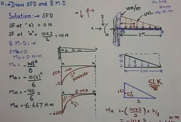
Sep 04, 2017 · here some of the points are very important to consider while drawing the sfd and bmd.
Sfd(shear force diagram) a shear force diagram is the graphical representation of the variation of shear force along the length of the beam and is abbreviated as s.f.d. P kn l/2 l/2 a b example 4. •beams classified according to the way they are supported. W = load per unit length, lbf/in or kn/m R = reaction load at bearing point, lbf or kn; Bmd(bending moment diagram) a bending moment diagram is the graphical representation of the variation of he bending moment along the length of the beam and is abbreviated as b.m.d. Steps to draw shear force and bending moment diagrams. I = second moment of area, in 4 or m 4; Bmd = bending moment diagram; Bendingmomentdiagram.com is a free online calculator that generates bending moment diagrams (bmd) and shear force diagrams (sfd) for most simple beams. V = maximum shear force, lbf or kn; 14) a 4 m long beam is shown in figure. Jul 17, 2017 · below are the beam formulas and their respective sfd's and bmd's;
Axial forces in beams ad and be are 10 kips and 15 kips respectively. M = maximum bending moment, lbf.in or knm; Sfd(shear force diagram) a shear force diagram is the graphical representation of the variation of shear force along the length of the beam and is abbreviated as s.f.d. In sfd and bmd diagrams shear force or bending moment represents the ordinates, and the length of the beam represents the abscissa. Sfd = shear force diagram;
2. SFD and BMD - CVG2140 Mechanics of Materials I Winter ... from www.coursehero.com I = second moment of area, in 4 or m 4; 14) a 4 m long beam is shown in figure. It carries a load of 12 kn applied through a bracket and also a udl for 8 m length from reight end. Example (3) draw the sfd and bmd for the beam acted upon by a clockwise couple at mid point solution: L = span length under consideration, in or m; Sfd(shear force diagram) a shear force diagram is the graphical representation of the variation of shear force along the length of the beam and is abbreviated as s.f.d. If p = 20 kn and l = 6 m, draw the sfd and bmd for the beam. 13) draw sfd and bmd for beam as shown below.
Which is a feature unavailable on most other calculators.
W = load per unit length, lbf/in or kn/m R = reaction load at bearing point, lbf or kn; Bmd(bending moment diagram) a bending moment diagram is the graphical representation of the variation of he bending moment along the length of the beam and is abbreviated as b.m.d. Bendingmomentdiagram.com is a free online calculator that generates bending moment diagrams (bmd) and shear force diagrams (sfd) for most simple beams. Example (3) draw the sfd and bmd for the beam acted upon by a clockwise couple at mid point solution: •beams classified according to the way they are supported. The beam is supported at each end, and the load is distributed along its length. E = modulus of elasticity, psi or mpa; 14) a 4 m long beam is shown in figure. In sfd and bmd diagrams shear force or bending moment represents the ordinates, and the length of the beam represents the abscissa. It carries a load of 12 kn applied through a bracket and also a udl for 8 m length from reight end. Axial forces in beams ad and be are 10 kips and 15 kips respectively. If p = 20 kn and l = 6 m, draw the sfd and bmd for the beam.
•beams classified according to the way they are supported bmd sfd. Bmd = bending moment diagram;